 These days, operators are faced with an increasing requirement to deploy in-building fiber broadband networks. The rising demand from consumers for superfast broadband services, coupled with the growing urbanization of the marketplace, means that many operators need to focus on installation efficiencies and effectiveness.
Bringing fiber into the building
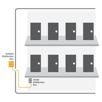
The first installation step is to get fiber cable into a multi-dwelling premise. It has to be routed from the point of presence (the outside distribution box in the example diagram below) into the building through the wall and plugged into a further distribution box or distribution frame in the basement or a comms room.
It is good practice to use cable that is UV-resistant and suitable for deployment indoors. Most optical fiber regulations allow for the installation of a short length of outdoor-rated UV cable within a building (check local regulations) of between two and 15 meters. However, if the cable needs to be routed further to reach the distribution box or frame, then a suitable LSZH, flame retardant or indoor-rated conduit/microduct should be used (this varies according to region).
There are a number of benefits to having the fiber distribution point inside a building. First of all, it extends the network lifecycle by increasing its protection – the fiber terminals and other passive equipment are no longer at risk of being damaged by harsh weather, negligence or vandalism.
Secondly, it speeds up the whole process of installation. It is common practice for network operators to route fiber cable from the basement of an apartment or office block up to floor boxes on each landing. This approach allows them to break out fiber quickly and cost-effectively when a resident demands it.
Choosing fiber cable connectors for in-building deployment
Irrespective of whether the network architecture is PON, point to point, or some other configuration, the fibers will need to be "connectorized" once they have been routed to the distribution frame (or, for small  scale MDUs, the distribution box).
The most popular connectors used in these environments are SC and LC with angled end faces - however, with larger buildings the scope for multi- ferrule connectors such as the MTP / MPO becomes more attractive - particularly in multi-floor point to point scenarios where each floor level box connects up to 12 subscribers. For further analysis on connector options, see: Fiber Connectors – what’s the difference.
When looking at the different ways in which operators can connect the distribution box or frame to floor level boxes, there are three main options available. Operators can use pre-terminated indoor drop cables, mechanical or fusion splice connectors, or they can splice onto pigtails. Each method has its pluses and minuses.
1. Pre-terminated fiber cable
Many small to medium network operators choose to use pre-terminated cable because it eliminates the capital expenditure, cost and required skills for time-consuming fusion splicing. As it is factory fitted and tested, a pre-terminated cable offers good, certified signal performance and, on top of this, no specialist staff or equipment is needed to install the product. However, the main drawback to using pre-terminated cable is that there may be excess cable during installation that needs to be coiled and stored within the route. However, operators can minimize this if they conduct proper site surveys.
2. Mechanical and fusion splice connectors
Recent years have seen a rapid expansion in the use of mechanical and fusion splice connectors. This rise is due to the lower initial capital expenditure (mechanical connectors only) compared to fusion splicing. The major disadvantage to using the mechanical connector is the high signal losses in comparison with fusion spliced or polished fiber connections. Fusion splice connectors offer better performance versus mechanical splice connectors but will require an expensive machine and the necessary components to adapt that machine to accept fusion connectors. Added to this, the technician needs to validate field assembled connectors using a suitable ODTR or light source and power meter, which adds extra time to the process.
3. Fiber pigtail fusion splicing
Fiber will inevitably need some form of connector, capable of repeat mating, and an outer protection rugged enough to allow repeat patching and switching. This activity increases the chance of optical loss at these points. Therefore, splicing on pigtails should only be done using high-quality pigtails and with proper splicing technique.
Increasingly, operators are using pre-terminated cable in multiple dwelling installations to remove weak spots, to preclude the requirement for highly-trained engineers, and to reduce installation times. As the uptake of FTTP services increases, the demand for efficient, effective and high-quality solutions will equally start to drive the business case.


