
Data Over Cable Service Interface Specification (DOCSIS) is an international telecommunications standard created by CableLabs, the non-profit research and development consortium for the US cable industry, along with contributing companies including Cisco, 3Com, Motorola and Intel.
DOCSIS is most commonly employed by cable television operators to facilitate high-bandwidth data transfer over an existing hybrid fiber-coaxial (HFC) infrastructure.
It’s also a vital element in providing network service providers and manufacturers with a framework that enables a range of products to work together in a predictable manner.
The consumer demand for new technologies, connected devices and bandwidth-hungry online applications is ever-increasing.
And the introduction of innovative augmented reality and virtual reality applications, will only continue to place even greater demands on upstream capacity.
With over 90% of US households already being serviced by coaxial cable, there is huge potential for DOCSIS technology to leverage the existing coaxial infrastructure and offer vastly improved network efficiency.
DOCSIS technology allows internet providers the opportunity to provide subscribers with an increase in internet speed without the need to replace or upgrade existing coaxial cable networks.
The DOCSIS specification does however also place higher performance demands on all the passive and non-digital components in the network including:
High performance will remain a priority for all companies that provide broadband connectivity solutions as they continue to meet customers’ demands for improved network capability.

DOCSIS specifications have continued to evolve to meet the needs of cable operators and broadband services consumers for higher speed access and improved network efficiency.
DOCSIS 1.0 - Comprised functional elements from existing proprietary cable modems, operating to a working limit of 38Mbps for downspeed and 9 Mbps for upspeed
DOCSIS 1.1 - Standardized the quality of service (QoS) mechanisms previously outlined in DOCSIS 1.0
DOCSIS 2.0 - Provided improved upstream data rates to meet increased demand for symmetrical services
DOCSIS 3.0 - Increased both upstream and downstream speeds by introducing channel bonding which enabled the combining of several downstream or upstream channels. Provided support for Internet Protocol Version 6
DOCSIS 3.1
Full Duplex DOCSIS 3.1 (FDX)
The completion of the specifications for Full Duplex DOCSIS 3.1 (FDX) in October 2017 provided significant improvements by:
/PPC_0123_eBook---How-to-Improve-In-home-Performance-DOCSIS309x289.png)
The DOCSIS architecture comprises two key elements:
In order for a cable company to be able to deploy DOCSIS 1.1 or above, it must first ensure that its its hybrid fiber-coaxial (HFC) network is interactive in that it can support a return path for upstream traffic.
Cable systems that support on-demand programming primarily use a hybrid fiber-coaxial system in which fiber optic lines carry signals to nodes where they are converted into radio frequency (RF) channels and modem signals.
The customer-premises equipment (CPE) connects to the cable modem, which in turn connects through the HFC network to the CMTS.
A CMTS device typically hosts downstream and upstream ports, with downstream and upstream communications travelling on a shared coax line and connecting to a single F connector on the cable modem.
It’s also common for the CMTS to have separate F connectors for downstream and upstream which provides flexibility for the cable operator.
Broadband Internet services place a lot of dependence on the return part of the spectrum (<50MHz) that can be loaded with signal interference from many electrical devices, caused by noise funnels.
Even though more recent upgrades to DOCSIS spread the load onto a wider portion of the spectrum, it’s still imperative that installers follow all of the best-practice guidelines for ensuring the best possible shielding inside a subscriber’s home to avoid putting ingress noise onto the return signal.
Not only is that where the hottest and most numerous sources of interference typically reside, it is also very hard to access at a later date to fix any leaks if they show up.
Careful handling and installation of cable and connectors; proper tightening of connectors to equipment; terminating or disconnecting unused ports and runs; and repairing or replacing cabling which has been embedded for years are the absolute most important things a technician can do on the equipment side.

When DOCSIS 3.1 was initiated in late 2013, it targeted greater capacity and increased speed for hybrid fiber-coaxial (HFC) broadband networks, while still remaining compatible with earlier technologies.
Delivering DOCSIS services, whether 64 QAM upstream (3.0) or orthogonal frequency division multiplexing (OFDM) 1024 (3.1,) is often possible with minimal investment and network changes.
However, to maximize delivery quality with the highest data speeds requires an in-home network that is resilient against interference and noise contributors.
As with any new technology or advanced spec, the success or failure of the roll-out lives or dies in the details of the reliability and robustness of the weakest component.
There are several obstacles to delivering DOCSIS technologies, including the common effects of loose connectors, signal level discrepancies and ingress/ egress.
In addition, the peripheral wireless technology long term evolution (LTE) is present in homes within the same spectrum (regionally specific) as broadband cable systems.
Negative effects from, for example, ingress and egress from coaxial cable shielding deficiencies and/or loose connectors with the presence of LTE transmissions can generate service calls, degrade the customer experience, and are increasingly monitored regularly.
Network architectures are evolving to include fewer homes per node, creating increased capacity per subscriber and delivering higher speeds. Fewer homes per node will improve performance through reduced return path noise funneling.
The actual bandwidth considerations vary geographically around the globe, and any modification to the network frequency allocation split between the forward and return path can come with a significant capital and operational cost.
To achieve the capacity demands required by the exploding adoption of data services, there is a natural evolution towards the deployment of more complex modulation techniques over DOCSIS platforms.
This has always been a leading indication that the overall network performance needs to improve.
The transitions from QPSK to 16 / 32 / 64 QAM over the years presented additional challenges that gave rise to common phrases, such as “drop hardening”, “home integrity check”, “proactive network maintenance” and “line conditioning”.
DOCSIS 3.1, utilizing orthogonal frequency division multiplexing (OFDM) modulation techniques and low-density parity check (LDPC) error correction, offers additional capacity per subscriber for a robust performing network - but maximizing the return on investment may require some efforts within the transmission medium.
/PPC_0123_eBook%20-%20The%20Complete%20Guide%20to%20Broadband%20Connectors309x289.png)

In-home network radio frequency (RF) performance plays a lead role in delivering services that meet service quality demands.
There are three main areas that impact today’s in-home network performance:
1) Quantity of Products/Services
With the increasing number of services and revenue generating units (RGUs) per home come additional components in the form of connectors, passive splitters, drop amplifiers, coaxial cables, modems and set-top devices.
Additional services/RGUs typically require passives which reduce signal carrier strength, allowing the infiltration of noise. It also increases the total cost of ownership (TCO) through more service calls - a systemic problem that is difficult to track for a single component.
There is a cumulative effect whereby more devices installed create additional noise, thus a greater funneling effect in the return path.
2) Quality of Components
The quality of the components used to connect multiple home devices impacts performance with respect to electrical integrity and component reliability.
RF ingress and egress from components that have poor RF shielding enable interference and noise that funnels in the return path to the head-end or cable modem termination system (CMTS). This RF noise degrades performance, increases error rates and diminishes the integrity of data flow.
3) Quality of Installation
The greater the number of components requiring installation, the greater the chance for installation errors. For example, when connectors are left loose or are improperly installed, the RF performance is negatively impacted.
With the increase in self-installations comes an increase in craft errors resulting in service calls.
Loose connections are also very susceptible to moisture ingress. The loss of continuity from loose connectors can significantly degrade signal return loss and insertion loss, creating reflections that generate data transmission errors and hinder performance.
Perhaps the most common service call condition is caused by loose connectors. Over 50 percent of all indoor connectors are less than finger-tight.
Often a connector may be loose with no continuity to ground, such that the connector post and nut are floating or uncoupled. This causes very high resistance and generates immediate signal level degradation, as well as cause ingress and egress.
Another common source of in-home performance degradation is low signal level. The overall signal level as a result of increased passives and associated passive loss may not be sufficient to deliver adequate performance, thus the need for amplification.
The removal of these obstacles, combined with architectural improvements, creates a path to and beyond the current DOCSIS 3.1 threshold requirement, to competitively deliver services that exceed consumer demand.
So with a few simple network investments you can have a successful deployment.
To control and increase in-home performance requires a focus on, and evaluation of, the components in place today.
It’s also vital to consider the current performance of all components, specifically the integrity of the F connectors, coaxial cable, passives (such as splitters), and F-81 line splices.
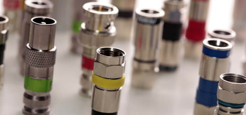
F Connectors
By far the most critical component in the home is the F connector. It is also the highest volume component in the network. For example, there are approximately 250 million CPE devices deployed in North American networks, containing over 3 billion F connectors.
The F connector is also the most common failure point, responsible for a significant operational cost burden that is magnitudes above the initial capital cost.
The high operational burden has become a focus of attention, with significant efforts being made to improve the technology and quality while reducing the associated installation craft errors.
The technology of the F connector has progressed over the years from a hex crimp design to a 360 degree compression design.
Furthermore, the physical design enhancements have created connector technology with a dynamic range of function.
This covers varying braid content from 60 percent coverage through to quad shield, with performance parameters exceeding recommended industry standards in some cases.
Proven field observations around craft errors and connectors that generate service calls have delivered further advancements in connectors over the past ten years.
However, it is still common to find older technology connector devices within the walls - i.e., located behind wall plates.
With connector improvements in mind, service offerings are placing more stringent requirements on this component within the in-home network.
With our field research showing over 50 percent of the indoor connections to be less than finger-tight or loose, the problem of loss of continuity to ground has gained high visibility with operators and installers.
In the one-way analog networks of previous years, loose connections had minimal to no impact, but this is no longer the case in today’s networks.
Loss of continuity occurs through loose connections where the connector hex nut is physically separated or intermittently disconnected from the connector post that extends within the grounding braid in the coaxial cable.
The loss of continuity creates an impedance mismatch, ingress / egress, high insertion loss and reflections that impede the data transfer. In fact, a single connector without continuity to ground can result in service calls at numerous homes within a single optical service area or “node.”
To minimize network impairments and service calls, it is essential to select an F connector that easily installs on all common cables in every environment and seals out moisture 100 percent of the time.
While there are many components contributing to in-home performance issues, the connector is often most vulnerable due to subscriber self-installs, device movement and common vibrations.
To address this operational burden, extensive research and monitoring of in-home networks worldwide resulted in the development of a connector that maintains continuity to ground even when loose.
When left loose, the continuity connector performs to a level near that of a fully tightened connector, minimally impeding network performance.
As such, it has been widely adopted by the largest global operators, is in millions of homes and is recognized as an enabler to better customer experiences and lower operational costs.
The figure below is a graph exhibiting a single loose connector with no continuity to ground.
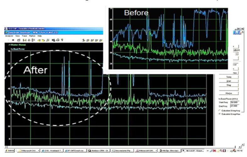
It shows the “Before”, affecting 200 homes in the return path and the resulting noise reduction in “After”, when the single suspect connector was tightened.
Deployment of continuity connectors is increasing, resulting in fewer service calls. In the example above, tracking codeword error rates (CER) improved when loose connectors were replaced with continuity connectors that were also left loose.
The difference in the example above is conclusive: immediate performance improvements were noted for the upstream CER and service calls were reduced.
Coaxial Cable
Today’s networks are demanding coax cable performance to 1.2 GHz, but legacy installed coax may only have adequate performance at a frequency specified below 1 GHz. Older coaxial cables should be verified as performing adequately.
The ingress effects caused by poor or damaged coaxial cable and poor or loose coaxial connectors within the home can generate service calls and service disruption affecting numerous subscribers.
The connector is often most vulnerable due to subscriber self-installs, device movement and common vibrations.
Passive Devices
When it comes to passive devices, specific parameters (electrical, bandwidth and physical) are designed into every solution.
These parameters, however, have changed over the years to evolve with the network demands.
We will now explore various passive devices and their performance threshold parameters:
Passive Splitters
Splitters may perform to adequate specifications (which include insertion loss and return loss) per their specified bandwidth.
However, the bandwidth requirements may have expanded since installation and these components may not perform well beyond 1 GHz or even to lower frequencies in the typical frequency range of 5 MHz to 860 MHz.
Due to inadequate performance at higher and lower frequencies than originally designed to, the bandwidth edges in which the network operates will be significantly degraded.
Passive Line Splices
F-81 splices, such as those located in wall plates, may be older and specified to a limited operating frequency.
With often more than five in every home (in wall plates and splices - that ALL look alike but with different specifications), it is difficult to identify the weaker links.
Return loss and center-conductor contacts are often not specified to current operating frequencies, again hindering performance for impedance, return loss and insertion loss.
Passives in General
Shielding effectiveness is another area where older or poor-quality passives may be installed but not be obvious during routine visits.
It is not generally desirable for technicians to replace poor coax within the walls of homes because of the operational cost burden. However, the network parameters and certification techniques within the home are starting to demand this.
Operators are now providing a home integrity checklist of performance parameters for service technicians and installers prior to closing out the service call or installation.
The checklist is becoming key in helping ensure that the vital parameters around signal integrity and data performance are met or exceeded.
These checklist parameters are a subset of the proactive network maintenance systems or standard operational practices (SOP) and have an overall positive impact on future home services and cumulative network performance improvement.
Finally, with the growing number of CPE devices and televisions per household, signal levels may require amplification due to the increase in the number of passives required.
The initial network build may not have considered the high level of passive loss or the loss increase due to higher bandwidth needs over time.
The signal levels at each CPE device may not be adequate to offer acceptable performance.
Passive MoCA Filters
There is also rising deployment of “whole-house” DVR services.
Some operators use a technology standard known as Multimedia over Coax Alliance (MoCA). MoCA operates at a much higher frequency and must be blocked via a low pass filter at the point of entry to the home.
Since strict “in-home” MoCA networks provide a secure transmission from DVR to client devices, it is a requirement to contain these signals in the subscriber’s home network and to prevent connection overlap with DVRs of neighboring homes.
Unfortunately, these low-pass MoCA filters add additional insertion loss, weakening the primary signal.
Drop Amplifiers
Drop amplifiers continue to be used to counter the effects of passive loss. Technicians must be sure to use the amplifier gain wisely and not attempt to cover other issues within the drop plant, such as excessive loss due to poor quality passives or damaged devices.
These issues could include damaged coax, loose connectors or passives that simply do not meet current bandwidth requirements.
Secondly, the bandwidth and the location within the in-home network of the drop amplifiers themselves are critical to overall system performance.
Finally, we should consider a passive port on the amplifier, also known as a bypass port.
This maintains VoIP and data transmission via the DOCSIS modem when there is no power in the home and ensures that the DOCSIS carrier remains above the noise floor.
Line Conditioning
There are passive and active devices to enhance signal levels over a broad frequency spectrum in the forward and return path bands.
These offer improvements by either filtering noise, blocking unwanted carriers that create interference, or switching the return path on and off to reduce the cumulative noise effects in the return path.
CPE devices require a signal level window to operate properly. When the signal levels exceed, fall below or both due to excessive tilt, the CPE fails to perform at optimum levels.
Frequency-specific devices, such as equalizers, cable simulators, attenuators, gain devices (drop amplifiers), and high / low pass filters, groom signals for optimum CPE performance.
Major operators are currently conducting further studies on the positive effects surrounding network performance and customer satisfaction.
/PPC_0123_eBook---Buyers-Guide-to-Quality-Connectivity309x289.png)
Hardening the drop improves in-home network performance by enhancing the signal-to-noise ratio, reducing impulse noise, and minimizing ingress and egress - all of which leads to a decrease in service calls.
Initial service calls often create follow-up service calls, and approximately 20 percent of repeat or follow-up service calls result in customer churn.
The operational cost of a service call almost always exceeds the capital cost, which is why it is so important that the drop hardening procedure is conducted efficiently at every visit.
Drop hardening involves three vital steps:
1) Identifying Root Causes
Root cause identification is important as it leads to product and process improvements. To control, stabilize and improve in-home performance requires a focus and evaluation of the components in place today.
These vary greatly from one home to another as a result of the initial installation, architecture required at the time of installation(s), and the variation of craft and component quality installed by operators and homeowners.
Today’s advanced proactive network maintenance (PNM) systems can often direct technicians to root causes, identifying loose connectors, moisture damage, inadequate or damaged coax, and passive components, to name a few.
Knowing the root cause provides valuable insight to drop hardening / performance improvements.
2) Benchmarking a Performance Threshold
A standard operational procedure outlining architectural guidelines and test parameters ensures a uniform approach is taken in order to reach the desired threshold.
Signal levels at the CPE, to include both forward and return, should be in the desired range.
DOCSIS levels from the cable modem should also be within the desired range as these vary greatly based on the passive loss variations in the return path. Signal to noise ratio (SNR) and modulation error ratio (MER) are also commonly tested.
Many of today’s PNM systems are constantly monitoring all network devices via DOCSIS parameters. Using logic, the operator is directed to issue areas that when repaired provide a cumulative performance improvement for numerous subscribers.
An integrity check can now be registered within the management system and monitoring continues automatically.
3) Evolving the Quality of Components
It is imperative to use quality components that meet or exceed current and future performance requirements. This involves upgrading devices with bandwidth limitations and ensuring that electrical / mechanical performance specifications are verified in accordance with network requirements.
Bandwidth limitations may vary greatly within the home from “hidden” components, such as the coax within the walls, to the simple splitters installed by the home owners to add additional devices (routers or TVs, for example).
The component quality must take into account the craft sensitivity of initial installations and reconnections commonly conducted by subscribers.
It is essential that products meet or exceed mechanical and electrical performance recommendations, not to exclude the areas of bandwidth (upper and lower frequency limits), RF shielding effectiveness, return loss, insertion loss and stability in varying environmental conditions.
/PPC_0123_eBook---MoCA309x289.png)