 There are numerous tasks involved in deploying fiber to the home (FTTH) technology and while some are obvious, others require more thought and consideration. In general, the tasks fall into three categories: preparation; installation and delivery; and measuring/verifying.
The design of an FTTx installation requires you to know the optical power required to reach the end user, to understand the conditions within the terminating premise, and to have details of the speeds and bandwidth required for each user.
1. Preparation
Depending on the factors cited above, you will need to work through several decisions. At a minimum for the drop network planning, gather the following information ahead of time:
- Signal power and performance requirements for each device or revenue generating unit.
- Locations of required splices.
- List of cable lengths required.
- A detailed map of the ducts with the space available in them.
- Cost efficient construction routes and obstacle planning.
- Regulatory approvals.
- Geographic survey of customer addresses (verified).
- In-house network installation plan with required approvals.
Once you have all the data above, you can begin to develop the timeline and plan for installation. The most complicated part of the planning process will be determining what is necessary to get the right signal levels at each device. The fiber network design and drop planning can be achieved with software, but will always require experienced network designers to maximize efficiency and check for feasibility.
2. Installation and delivery
Once planning is completed, schedules and routes created, and resources prepared, the installation can begin. The main components you will need to be working with are below. Each requires the right tools, techniques and planning:
- Fiber optic cables.
- Splice closures.
- Optical splitters, connectors and adapters.
- Demarcation enclosures.
- Optical patch panels for fiber drop cables and associated patch cords.
The following are standard activities in a fiber installation that should be performed and planned for accordingly:
Labeling
Accurately label patch cords, multicore cables, fiber drop cables and optical modules.
Fiber cable arrangement
Route the fiber cable into the cabinet based on the passives to connect to and arrange the cables in the tray in circular loops. Secure the cables using Velcro straps.
Patch cord installation
Use the right patch cord lengths, connect passive splitting output ports to corresponding patch panel ports. Route the patch cord in the cabinet or pedestal and secure.
Cable tray for cable loops
Suitable cable loops must be maintained with proper bend radius to avoid strain on the cable when accessing the passives.
Fiber drop cable installation
Use low friction and crush proof indoor/outdoor cable, plenum and riser as required with moisture resistance. Cables must be pulled/pushed/blown to the proper connections and connectors installed.
BE SURE TO:
- Minimize the distance of cable pulls not to exceed the limits shown in the network design.
- Added attenuation will hinder performance.
- Follow manufacturer’s recommendations for cable bend radius when pulling the cable.
- Use low force when pulling cable.
- Bundle cables neatly and secure properly.
BE SURE NOT TO:
- Pull the cable beyond its pulling tensions.
- Bend or kink cable.
- Tie fiber cable too tightly.
3. Measuring/verifying
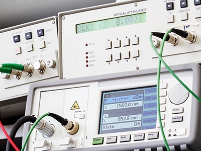
Obviously, you want your fiber drop to perform well and the best method to achieve this is by carefully measuring and evaluating the light signals at each point in the drop network. Some useful tools for gathering information about your installation will be optical power meters and OTDRs.
Verify the optical signal level at end user locations comparing the measurements to the design maps. The end-to-end check requires testing or verifying a few things of importance: length of fiber, insertion loss (IL) and optical return loss. Various devices may have unique requirements for power in/out and return loss.
The end-to-end loss is dependent upon a specified wavelength and includes the connectors on each end, the loss of the fiber in each link, the connectors or splices on the splitter and the loss of the passive filters and splitters.
Using CWDM or DWDM? If the fibers are being used bi-directionally and connector or splice losses are different in each direction, testing in both directions is necessary for verification. Measure the loss at relevant wavelengths and keep OTDR traces as they are important for installation verification. These will be used for future reference surrounding network stability and troubleshooting.