


 We all regularly talk about Fiber to the Premise (FTTP)/Fiber to the Home (FTTH) networks. But, in an era of specialization, often we only know about the parts we come into contact with during our working lives - such as the last drop connection, in the case of installers.
What’s in an FTTP network and how does it work?
In FTTP network is made up of two main parts:
- Physical layer
- Active optoelectronics (central office, outside plant and customer premises)
The ITU-T standard helpfully defines the extent of a fiber network through the G series of recommendations. G.984.2 is the most relevant here as it covers GPON networks, and we'll discuss PONs throughout this blog.
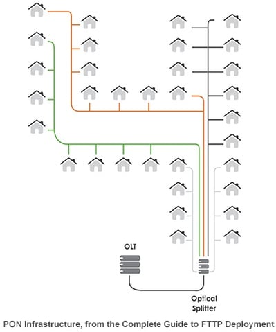
Optical Line Terminal (OLT)
The start of the network is the optical line terminal (OLT). It converts the traffic in the carrier’s internal backbone network to the optical wavelengths and framing structure used by the PON. It also receives and combines ("multiplexes") the signals from the customer’s network end point - the optical network unit/terminal (ONU/ONT).
Within the OLT equipment are a CPU, gateway router, and network cards. The incoming fiber line interfaces to the OLT via a small form pluggable (SFP) transceiver.
In many cases, the carrier does not want to hard wire a customer to an OLT. They may leave, require a different service or there might be a need to re-route their line due to physical changes to the network. Instead, they’ll use an optical distribution frame (ODF) to provide connectorized or spliced connections between fibers from the two domains.
Another function that can be performed at the ODF is to insert passive optical components, such as couplers, to enable traffic on different wavelengths to be combined.
Splitting the Fiber
To move from a single fiber to supply multiple points, the fiber naturally needs to be split. For a PON network, it's possible to split the fiber at the central office, or at one or more points within the network, such as the ODF. This is achieved through fiber splitters.
While splitting at the central office removes the need to house any components in the field it requires the deployment of a lot of fiber, which needs to be added to the network. This means in the majority of cases, splitters are deployed closer to the customer. They are usually placed strategically to maximize the shared use of a single fiber and minimize the distance from the split point to individual customers since this fiber is dedicated, not shared.
Splitters operate by dividing incoming light into two or more paths. The signal is usually divided so that the same distribution of wavelengths travels in each downstream path. Splitters come in two fundamental types: fused biconical taper (FBT) and planar lightwave circuit (PLC).
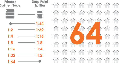 They are typically one or two split points, and from the final location, the all-important last or final drop is created. Networks often support a split ratio of 1:64 to each customer, although the G.984 standard will support up to 1:128 splits. 1:64 is useful in terms of architecture because as well as still offering relatively good bandwidth to each end-user, it is also achievable in a number of ways.
The Last Drop
There are probably more types of drop cable than any other sort. These range from direct buried non-terminated, to buried and pre-terminated, blown (terminated or not) and multiple aerial designs. Again, the ITU-T’s specification (L.87) provides a good introduction. The current trend is to use dual purpose indoor/outdoor fiber optic cables; rugged enough for outdoor use, but sufficiently fire retardant to meet safety requirements within buildings.
The drop cable normally enters the premises and completes the network at the ONU/ONT. This means the ONU is usually the only part of an FTTP deployment that the customer sees. It converts optical signals to the electrical domain, manages the connection to shared PON and provides outputs to devices such as TV, broadband connectivity, and plain telephony.
This general layout of PON FTTP networks is likely to persist for some time. However, as discussed in another blog, wavelength selective filters will be utilized in NGPON2, altering things slightly. Whatever your role in deploying fiber, having an overview of the whole network helps. By understanding the bigger picture, you can make more informed choices when planning and installing the last drop to ensure it's successful, reliable and cost-effective.